 Basic TMN architecture (functional blocks) & reference points:
Last update PvD
5 Generic Components & Interfaces
Overview
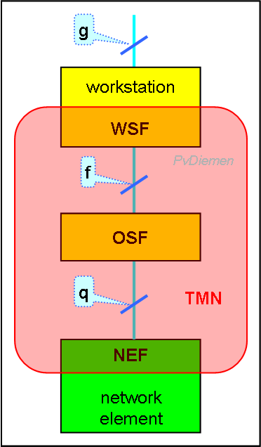
A TMN Operations System (OS) is build from the following TMN function blocks [M.3010]:
One could say that the network is modelled for management purposes. It also means that if particular parts are not modelled, they can not be managed.
Interfaces between functional blocks are called 'reference points' and indicated by letters; lowercase for generic interfaces {types/classes}, uppercase for instantiations {actual implementations}.
Basic TMN architecture (functional blocks) & reference points:
Note that the 'g' reference point is the Human/Machine Interface (HMI); it is specified for reference purposes, but is not subject to TMN standardization (so it is outside TMN).
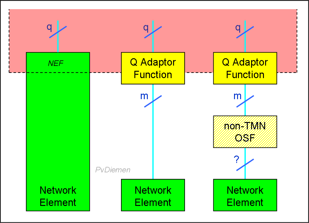
Realizing that many simple and/or existing Network Elements will not have an interface according to the 'q'-interface standard, a specific q adaptation function is defined: [M.3010]
 QAF
QAF
The 'm' reference point is not part of TMN standardization. The interface will typically be an existing proprietary management interface.
Also, Network Elements may have a q-like interface, but not fully up to standard (protocol, information model). There are three levels of compatibility defined for the q-reference point: q1, q2 and q3 (the full interface). The q-like interfaces (q1 or q2) are indicated as qx reference point, whereas the full standard q-interface is indicated as the q3 reference point.
For q-like cases a general adaptation function is defined: [M.3010]
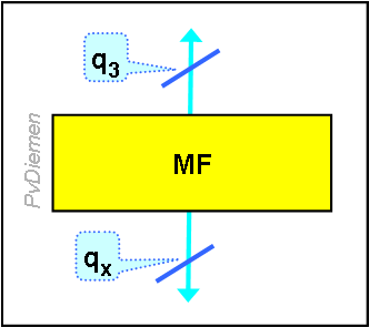 Mediation Function
The MF is similar to the QAF; the difference is that an MF converts a qx-interface (i.e. a publicised interface, but not entirely according to standard protocol), and the QAF converts an m-interface (i.e. proprietary interface). A QAF may contain a MIB.
There is not much difference between an MF and an OSF; both have manager/agent functionality, and the MF may even include a MIB. The difference is in the purpose: an MF is to adapt the Information Model; an OSF is to manage the network.
Any non-trivial OSF will consists of multiple application functions i.e. multiple OSFs. The interface between OSFs is q3 unless the OSF is in a different TMN (i.e. from another operator or a customer) or a non-TMN system: than it will be an x-interface. The main difference between a q3 and an x reference point will be the restricted access. The 'x' reference point is subject to ITU standardization.
This leads to the following example of TMN architecture (functional blocks) & reference points (generic interfaces):
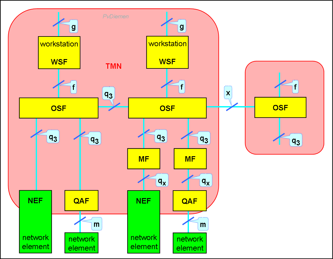
A large network will offer many services; a TMN for such a network will have Element Managers and Network Managers per type of element, and many Service Managers. That is to say that there will be multiple OSFs, mostly interconnected.
When implemented (i.e. when instantiated), management functions become processes, and reference points become interfaces.
Combining the TMN architectural layers with the reference points results in the following picture:
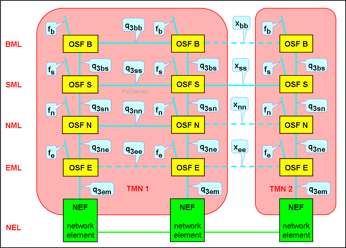
Note that Qxx and Xxx interfaces suggest symmetry, but that is not necesarily the case. See [X.701 fig 5], also chapter Concepts section Peer-to-peer.
When the Information Model is defined at a particular level, the suffix can be replaced by the indication of the Information Model. For example: if the network element is a Local Exchange, q3em can be replaced by Q3LE: Q3LE is an instantiation of q3em.
When both TMN systems are from distinct operators, it is unlikely that the interfaces Xee, Xnn and Xbb will exist. Network management interaction will be at the service level (SML), so Xss will exist. Similarly within a TMN, Qee is highly unlikely.
Note that the foreign TMN can be from another (Service) Operator, from a Service Provider or from a Customer (CNM).
In order for the TMN to reach all dispersed components (various OSFs, and of course the NEs), it will need a network. This network is kept separated from the managed network, and is called the Data Communication Network (DCN).
The reasons to keep the DCN separate from the managed network are simple: not all networks are suitable for management communication, and it avoids that problems in the managed network impede on management communication. Also, the chances for intrusion from the managed network into the DCN are severely reduced.
Of course this DCN needs to be managed as well (GM).
|
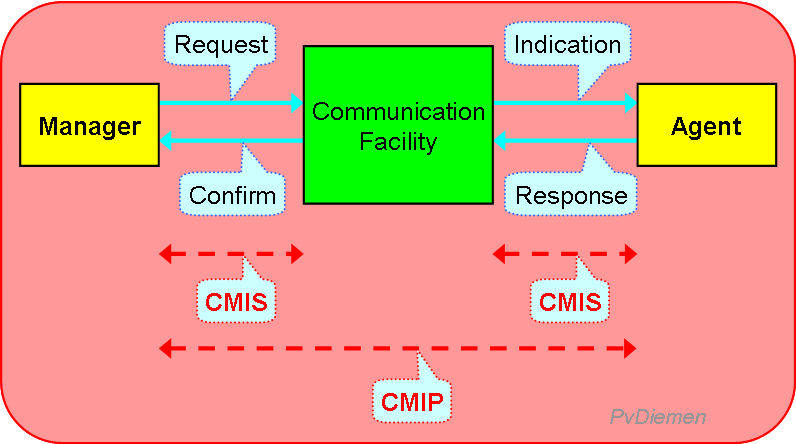
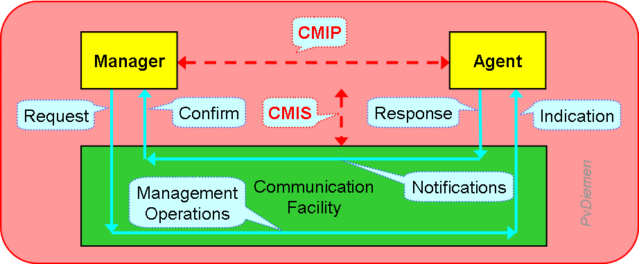
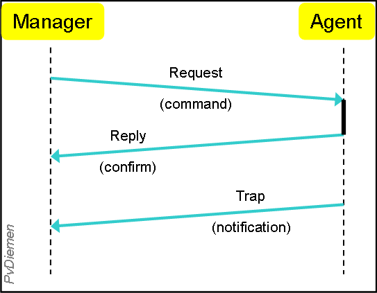
The Common Management Interface Protocol (CMIP) defines the communication interaction between a Manager and an Agent: [X.711]
The interface between application (OSF: Manager or Agent) and the communications facility is called Common Management Interface Service (CMIS) [X.710].
|
|
Management operations services:
| M_CREATE | Request a peer CMISE user to create an instance of a managed object. |
| M_DELETE | Request a peer CMISE user to delete an instance of a managed object. |
| M_GET | Retrieval of management information from a peer CMISE user. |
| M_CANCEL_GET | Request a peer CMISE user to cancel a previously requested and now outstanding invocation of M_GET. |
| M_SET | Modification of management information to a peer CMISE user. |
| M_ACTION | Request a peer CMISE user to perform an action. |
| M_EVENT_REPORT | Report an event about a managed object to a peer CMISE user (commonly a manager has previously set a trigger for the object at an agent).
An alarm is a special case of an event_report (see Alarm Reporting X.733). |
Management Information may be viewed as a collection of managed objects, each of which has attributes, and may have defined events and actions (i.e. actual CMIP/CMIS transactions involves an Information Model). Names of instances of managed objects are arranged hierarchically in a management information tree (see MIB).
Managed object selection involves two phases: scoping and filtering.
Scoping entails the identification of the management object(s) to which a filter is to be applied. Scoping is defined for:
CMIP/CMIS provides for many parameters (like scoping, filtering, synchronization) which has to be negotiated during the association establisment (A_ASSOCIATE of ACSE, X.217).
We will not go into those details here.
CMIP is a Management Application Protocol (MAP); the management information which appears in the CMIP message (the Protocol Data Units (PDU), i.e. the message fields) are called Management Application Protocol Data Units (MAPDU).
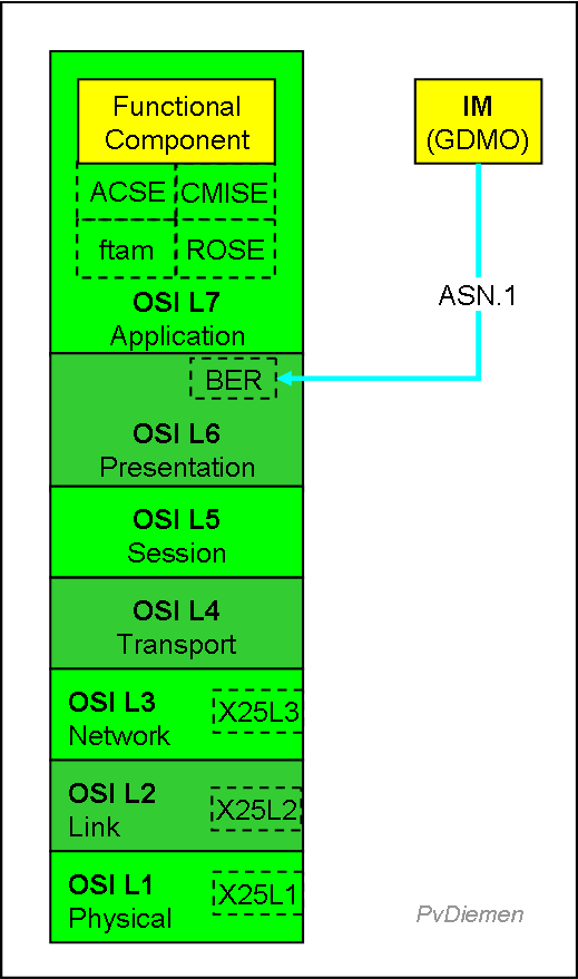
Communication between TMN functional components is via the Message Communication Function (MCF; OSI L5) and Data Communication Function (DCF, OSI L3):
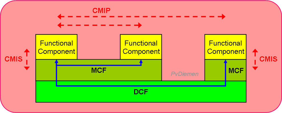
In practice, a lot of DCNs use CMIP over TCP/IP (CMOT).
The communication association between the Operations Systems Functions (OSFs: Manager or Agent) is not part of CMIP/CMIS but handled separately by the Association Control Service Element (ACSE) (X.217).
ASN.1, BER
GDMO
A Management Information Base defines the Management Objects (MO) available for network management. It uses ASN.1 notation to define these objects. In order to use a MIB, one must have access to that definition; to that end MIBs are commonly publically registered (but it is of course possible to define private MIBs).
All registered MIBs are ordered in a tree; the MIB-number identifies the branches. It shows the issuing authority, and allows easy extensions. The following depicts a part of that tree.
─┐
 ├─0─── CCITT
 ├─1─┬─ ISO
 │   ├─0─── Stnd
 │   ├─1─── Reg-Auth
 │   ├─2─── MB
 │   ├─3─┬─ ORG
 │   │   ├─6─┬─ DOD
 │   :   │   ├─1─┬─ Internet (IAB)
 │       :   │   ├─1─── Directory
 │           :   ├─2─┬─ MGMT
 │               │   ├─1─┬─ MIB-2
 │               │   │   │ (object groups)
 │               │   :   ├─1─┬─ System
 │               │       │   ├─1─── sysDescr
 │               │       │   ├─2─── sysObjectId
 │               │       │   ├─3─── sysUpTime
 │               │       │   ├─4─── sysContact
 │               │       │   ├─5─── sysName
 │               │       │   ├─6─── sysLocation
 │               │       │   ├─7─── sysServices
 │               │       ├─2─── Interfaces
 │               │       ├─3─── AT {Address Translation}
 │               │       ├─4─── IP {Internet Protocol}
 │               │       ├─5─── ICMP {Internet Control Message Protocol}
 │               │       ├─6─── TCP {Transfer Control Protocol}
 │               │       ├─7─── UDP {Unreliable Datagram Protocol}
 │               │       ├─8─── EGP {External Gateway Protocol}
 │               │       ├─10── Transmission
 │               │       ├─11── SNMP
 │               ├─3─── Experimental
 │               ├─4─┬─ Private
 │               │   ├─1─┬─ Enterprises
 │               :   │   ├─9─── Cisco
 │                   :   ├─11── HP
 │                       ├─23── Novell
 ├─2── Joint ISO/CCITT   │
 │                       :
 :
In fact, this registration allows identification of each (MIB-)object via numerical identifiers, via MIB and object group to an individual object.
When indicated by a lowercase letter, it indicates the generic reference point; when indicated by a capital letter, it indicates a particular interface to instantiated objects complying to the standard. A q-interface is a generic/functional reference point; a Q-interface is an actual/physical interface using the specified MIB.
A q-reference point defines two things:
There is no standard Q3 for all Network Elements, but there are standard Q3 instances for each type of Network Element. For each type of NE there should be an Information Model, whether it is standardized (i.e. Q3) or not (i.e. Qx). A particular Q-interface also assumes a particular information model (IM). For example: QbLE indicates the Information Model for the broadband Local Exchange, which is not (yet) standard, but an extrapolation of the narrow-band Local Exchange IM.
The exact protocol is hardly a problem as long as CMIP interaction is used (there are variants using Ethernet, or CMIP over TCP/IP: CMOT). Also, the use of the full protocol stack has some performance drawbacks: ASN.1 encoding/decoding requires additional processing and is verbose (long messages, slow transfer).
However, when another Information Model is used (i.e. proprietary model, but potentially OSI-stack), the interface is not compatible ! This is much more of a problem, in particular as IMs for most Network Elements are not (yet) standardized or only rudimentary. So for the moment: if it is Q3, it is insufficient ! Standardization will require a lot of effort and result in even more effort to develop alll adaptation and mediation.
A q3 protocol stack (level 4..7 full OSI) will look like:
More or less in parallel with ITU's/ISO's TMN concept, the Information Technology (IT) world has developed its Simple Network Management Protocol.
Its origin is in the computer networks, i.e. the LANs, but as these have grown into quite complex WANs, the purpose of SNMP is much broader.
TMN managed networks on the other hand, is now also interfacing to Customer Premises Equipment (CPE), and with the advent of Virtual Private Networks, the demarcation between public and private networks becomes blurred.
Quite often, management of CPE is outsourced to the public operator, i.e. the public operator has to manage SNMP-managed equipment. Also, access equipment for the public network is often implemented with SNMP-managed equipment (i.e. multiplexor or router). And when a customer moves from a private network to a Virtual Private Network, he has to interface to TMN managed networks or request an SNMP interface.
Some years ago, there was a debate which way to go: TMN or SNMP.
Now it is clear: for a large network you have to do both !
It is not a real problem, conceptually they are very similar: both use the manager/agent-concept and a MIB. The difference is for a large part in terminology.
And don't be fooled by the name Simple Network Management Protocol; implementing it is not simple. The intention was to create a simple protocol, but to cover all kinds of data protocols and equipment the result is not straightforward.
This can be attributed to the fact that Network Management is never simple (unless your network is simple, but then, who needs network management).
There are two versions of SNMP: version 1 and version 2, commonly denoted as SNMPv1 and SNMPv2 respectively. Most of the changes in Version 2 increase SNMP's security capabilities (still there is only weak control over objects). Other changes increase interoperability by more rigorously defining the specifications for SNMP implementation. There is also a minor change in frame layout. It is expected that after a relatively brief period of co-existence, SNMPv2 will largely replace SNMPv1.
|
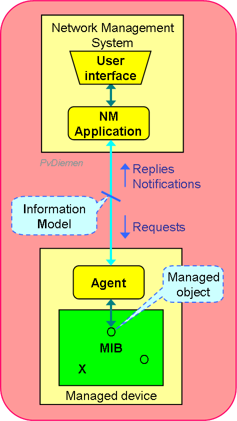
The management (reference) model used by SNMP is similar to the OSI model:
Note that this is a non-layered approach, i.e. no cascading of Information Models or Manager/Agent-relationships. In SNMPv2 however, a NM-Application can Inform another NM-Application, and one is free to define a private MIB for a particular NM-Application, so it is possible to design a layered application. And nobody will stop you if you use TMN concepts on higher layers (but you might experience other limitations). SNMPv2 has the notion Party; it allows multiple managers with security features. Because there is an open interface (no DCN), in practice most MIB components are read-only; control via SNMP –and thereby active management– is severely limited.
 |
|
Basic management operations (SNMP transactions):
SNMP does not provide equivalents for CMIS M_Create, M_Delete, M_Cancel_Get (looks superfluous in SNMP) and M_Action; most might be resolved using special set-commands.
Communication transport for SNMP is UDP/IP (unconfirmed !) in stead of X.25 (or CMOT: CMIP Over TCP/IP). Because of that, it is common to execute a 'Resynchronization'-command to make sure that the status of alarms between Network Manager and Agent are consistent.
With SNMP it is common to use autodiscovery of objects, i.e. a trap may indicate an object new to the manager, which may cause the manager to get more information on that object.
It suggests that in SNMP-managed networks (typically LANs) it is less important when an object (e.g. a workstation) doesn't register.
Also, it is common to use the same physical link for management as for normal communications (whereas in CMIP-managed networks it is common to have a separate physical link for management operations: DCN).
Identification (naming) in SNMP is through IP-addresses (whereas in CMIP there are various options, e.g. Fully Distinguished Name).
The Structure of Management Information (SMI; i.e. the notational techniques for MIBs) for SNMP are defined in RFC1155 and RFC1212 (whereas for CMIP/OSI this is defined through GDMO). {However, these are equivalent ?} SNMP uses the same MIB definition technique: SMI, BER, ASN.1.
Message formats between SNMPv1 and v2 are slightly different.
The following limitations are mentioned in ["Network Management of TCP/IP networks: Present and Future", IEEE Network Management July'90 by A.Ben-Artzi, A.Chandna, and U.Warrier].
Many of these deficiencies are addressed by OSI network management. Some, however, consider this as a case of the cure being worse than the disease, given the complexity and sheer size of OSI network management. Improvements to SNMP, especially in the area of security, are in the pipeline. It remains to be seen whether these improvements will have the widespread vendor and customer support of SNMP or whether both vendors and customers will by and large stick with 'basic SNMP' until making the big jump to OSI network management.
Note 1: SNMPv2 includes a Get_Bulk command, which may resolve this (partly).
Transaction Language 1 –or TL1– originated in the US to control network elements. It is a Command Language (i.e. Man-Machine language) but it is also suitable for Machine-to-Machine purposes. TL1 is popular for Inventory and Service Provisioning (i.e. CM), and for Testing (i.e. FM). TL1 does not prescribe any lower layer protocol, but nowadays it is most likely IP.
TL1 has only 4 message types, each with a fixed format, but messages/commands can be extended (e.g. by network vendors to cover their functionality). The message types are:
| Command code | Staging block | Payload block | |||||
|---|---|---|---|---|---|---|---|
| Verb | Modifier1 | Modifier2 | TID | AID | CTAG | General block | Data block |
| Response Header | Response Id | Response block | Terminators | ||||
|---|---|---|---|---|---|---|---|
| SID | Date | Time | M | CTAG | Completion code | ||
| Acknowledgment code | CTAG | Terminator |
|---|
| Auto Header | Auto Id | Auto block | Terminators | ||||
|---|---|---|---|---|---|---|---|
| SID | Date | Time | Alarm code | ATAG | Verb | ||
| TID = Target identifier SID = Source identifier | a unique name assigned to each NE |
| AID = Access identifier | identifies the object within an NE |
| CTAG = Correlation tag ATAG = Autonomous correlation tag | numbers used to correlate messages |
The generic Operations Systems components:
Communication is via:
Reference points define a protocol (standard CMIP) and an Information Model. Reference points are:
When an interface is denoted by a lowercase letter, it indicates the generic reference point class; when indicated by a capital letter, it indicates a particular instance (i.e. according to the MIB indicated in the suffix).
{Example of multi-network (VAS) by 1 operator, Multi operator TMN, CNM}
Next section: System Management Functions
Up to Contents
Up to Index
=O=